|
|
||
|---|---|---|
| .. | ||
| main | ||
| Makefile | ||
| README.md | ||
| partitions.csv | ||
| sdkconfig.defaults | ||
README.md
Camera with Command Line in Single Chip
This example demonstrates Human Face Detection with a single ESP32 chip (without using any LCD module). ESP32 firstly gets images that are captured by the camera module, then determines if there are any human faces as well as displays its Detection Results in the Serial Terminal.
Preparation
To run this example, you need the following components:
- An ESP32 Module: ESP32-WROVER, which we highly recommend for beginners, is used in this example.
- A Camera Module: the OV2640 image sensor, which we highly recommend for beginners, is used in this example.
- SDKs:
For the detailed introduction about preparation, please see here.
Quick Start
After you've completed the hardware settings, please follow the steps below:
- Connect the camera to ESP32 module;
- Flash Applications to ESP32;
- Start Human Face Detection and Check Detection Results.
Connecting
The table below lists the specific pins used in this example for connecting the ESP32 module and the camera module.
| Interface | Camera Pin | Pin Mapping for ESP32-WROVER |
|---|---|---|
| SCCB Clock | SIOC | IO27 |
| SCCB Data | SIOD | IO26 |
| System Clock | XCLK | IO21 |
| Vertical Sync | VSYNC | IO25 |
| Horizontal Reference | HREF | IO23 |
| Pixel Clock | PCLK | IO22 |
| Pixel Data Bit 0 | D2 | IO4 |
| Pixel Data Bit 1 | D3 | IO5 |
| Pixel Data Bit 2 | D4 | IO18 |
| Pixel Data Bit 3 | D5 | IO19 |
| Pixel Data Bit 4 | D6 | IO36 |
| Pixel Data Bit 5 | D7 | IO39 |
| Pixel Data Bit 6 | D8 | IO34 |
| Pixel Data Bit 7 | D9 | IO35 |
| Camera Reset | RESET | IO2 |
| Camera Power Down | PWDN | IO0 |
| Power Supply 3.3V | 3V3 | 3V3 |
| Ground | GND | GND |
The pin mapping will be slightly different if you use other ESP32 modules.
In particular, if you are using a ESP-WROVER-KIT for your development, whose camera connector is already broken out (the one labeled Camera / JP4), please follow the steps below:
- Plug your camera module, i.e. the OV2640 module in this example, on the board;
- Connect the 3V3 and GND pins on the camera module to those counterparts on the board.
The image below shows a ESP-WROVER-KIT development board with a OV2640 camera module installed on it.

Flashing to ESP32
Please see here.
Checking Detection Result
- Put your camera module away from a human face for at least 0.3 meter;
- Open a Serial Terminal by using the command line
make monitor; - Check result at your Serial Terminal, and you will be able to see information displayed in the screenshot below:
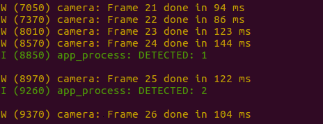
The keyword DETECTED appears whenever ESP32 detects a human face.
Advance Configuration
In this example, several parameters can be configured by customers to better support different customized scenarios. For the detailed description of these parameters, please see Here.
Besides, please see below for the recommended configuration for general-purpose scenarios:
mtmn_config.min_face = 80;
mtmn_config.pyramid = 0.7;
mtmn_config.p_threshold.score = 0.6;
mtmn_config.p_threshold.nms = 0.7;
mtmn_config.r_threshold.score = 0.7;
mtmn_config.r_threshold.nms = 0.7;
mtmn_config.r_threshold.candidate_number = 4;
mtmn_config.o_threshold.score = 0.7;
mtmn_config.o_threshold.nms = 0.4;
mtmn_config.o_threshold.candidate_number = 1;