8.3 KiB
ESP-EYE Getting Started Guide
中文(../../ zh_CN/get-started/ESP-EYE_V2.0_Getting_Started_Guide.md)
What You Need
- 1 × ESP-EYE V2.0 board
- 1 × Micro USB cable
- 1 × PC loaded with Windows, Linux or Mac OS
Overview
ESP-EYE is an ESP32-based development board that integrates a digital microphone, 8 MB PSRAM and 4 MB flash, as well as provides an external 2-million-pixel camera, which makes the board very suitable for applications in the fields of face detection, face recognition, and speech recognition. Besides, the board can also support image transmission over Wi-Fi and debugging using the Micro USB port, which enables the users' development of advanced AI solutions.
Hardware Preparation
The list and figure below describe the key components, interfaces, and controls of the ESP-EYE development board:
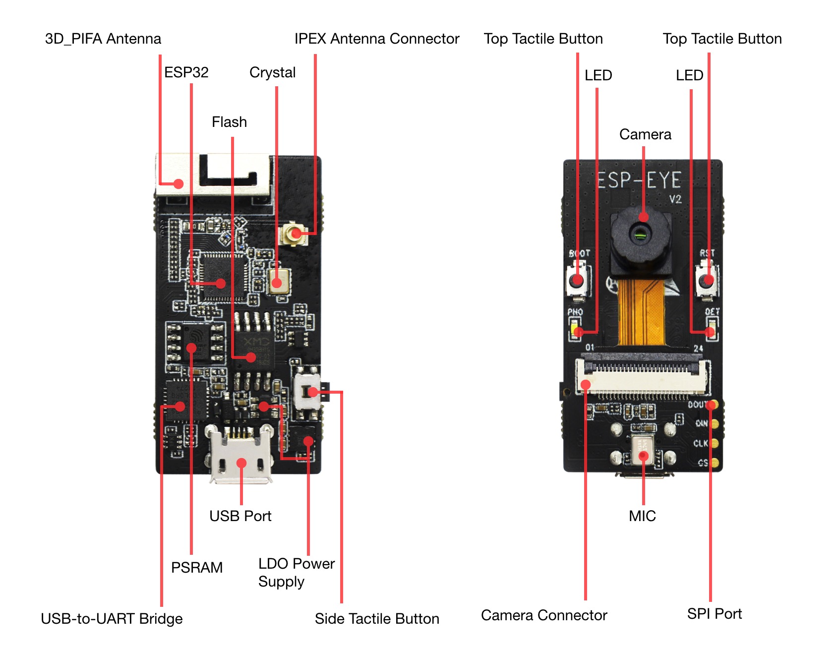
-
3D_PIFA Antenna
A 3D PIFA antenna. Users can choose the R14 resistor to select external IPEX antenna or choose the R15 resistor to select the 3D antenna.
-
IPEX Connector
Used for connecting external IPEX antenna. Users can choose the R14 resistor to select external IPEX antenna or choose the R15 resistor to select the 3D antenna.
-
ESP32 Chip
A 2.4 GHz Wi-Fi and Bluetooth combo chip
-
Crystal Oscillator
Provides an external clock for ESP32.
-
Flash & PSRAM
Provides memory to store applications.
-
CP2102 USB-to-UART Chip
Converts the USB signals to UART signals.
-
USB Port
Provides the power supply to the whole system.
-
LDO Power Supply
Provides the required power supplies to the ESP32 chip, camera and LED indicators.
-
Side Tactile Button
A function key
-
Top Tactile Button
Reset/Boot button. We recommend that you do not configure this button for other uses.
-
LED Indicators
The board has a red indicator and a white indicator. Different combinations of red and white indicators reflect the different status of the board, such as waking up, networking, face detection, face recognition, face enrollment, and face recognition...
-
Camera
An external 2-million-pixel camera module for face detection, face recognition and Face ID enrollment
-
Camera Connector
Used to connect the external camera.
-
MIC
A digital microphone for voice control functions
-
SPI Port
A reserved port for data transmission
Software Development
ESP-EYE supports firmware downloading with a PC loaded with Linux, MacOs or Windows operating systems. For now, users must set up toolchain in the development environment before starting the software development.
Preparation
- Go through Get Started to set up toolchain in your PC;
- Connect ESP-EYE to your PC with a Micro USB cable;
- Launch your development environment tool, such as Terminal (Linux/MacOS) or MinGW (Windows).
Get ESP-WHO
To obtain a local copy: open your Terminal (such as Terminal in a Linux environment), navigate to the directory you want to put ESP-WHO, and clone the repository using git clone command:
git clone --recursive https://github.com/espressif/esp-who.git
ESP-WHO will be downloaded into an automatically generated folder named esp-who.
Do not miss the
--recursiveoption. If you have already cloned ESP-WHO without this option, please run another command to get all the submodules:git submodule update --init --recursive
Set UP Path to ESP-WHO
Please follow the instruction described in Setup Path to ESP-IDF to configure the IDF_PATH variable to esp-who/esp-idf.
Download Firmware
This section describes the steps to download firmware to ESP-EYE (taking the Linux operating system as an example):
- Power up ESP-EYE by connecting it to your PC with a USB cable.
- Run
ls /dev/ttyUSB*in your Terminal to check if the board has connected itself to your PC successfully. You will see a newly generated item named something like/dev/ttyUSB0in your list after running the command if the connection is successful. - Navigate to an example directory, such as
cd esp-who/examples/single_chip/recognition_solution. - Run
make defconfigto complete default configuration. - Run
make menuconfig, and go toSerial flasher config->Default serial portto configure the device name to the item you saw in the second step, something like/dev/ttyUSB0. Then, save and exit. - Run
make flashto download firmware.
Check Logs
This section describes the steps to check logs with your Terminal (taking the Linux operating system as an example).
- Launch your Terminal;
- Run
make monitor.
Note: The ESP-EYE development board will reboot after this operation.
Key Process
The figure below describes the workflow of ESP-EYE:

1. Voice Wake-up
ESP-EYE awaits to be woken up after powering up (Red LED on and white LED off). The board wakes up after recognizing the wake-up command "Hi Lexin", then awaits for networking (Red LED flashing and white LED off). Now, users can initiate the networking.
2. Networking
Users can connect their PCs or mobile phones to ESP-EYE's Wi-Fi with the following information (by default):
- Username: esp-eye-xxxx (xxxx indicates the board's MAC address)
- Password: no needed
Alternatively, users can also follow the steps below to configure the username and password of the board's Wi-Fi:
-
Launch your Terminal;
-
Run
make menuconfig, and complete the configuration as instructed in the figure below: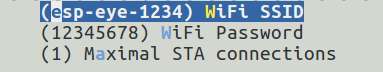
Note: You will have to restart from the step of downloading firmware after you have reconfigured the Wi-Fi username and password.
3. Face Detection
ESP-EYE starts the face detection after networking. Users can see the real-time image, captured by the board, with their browser (address: 192.168.4.1/face_stream). During this, the red LED is off and the white LED is on.
4. Face Recognition
After detecting a face, ESP-EYE will start the face recognition if there are any enrolled Face IDs stored in the board:
- When there is a match: the red LED on the board flashes once, and the browser displays HELLO ID XXX.
- When there isn't any match: the board shows no signs, and the browser displays WHO?”.
If there isn't any enrolled Face ID, the board continues face detecting. Therefore, please at least enroll one Face ID if you want to start the face recognition.
5. Add/delete a Face ID
The users can add/delete a Face ID after the network is successfully established.
5.1 Add a Face ID
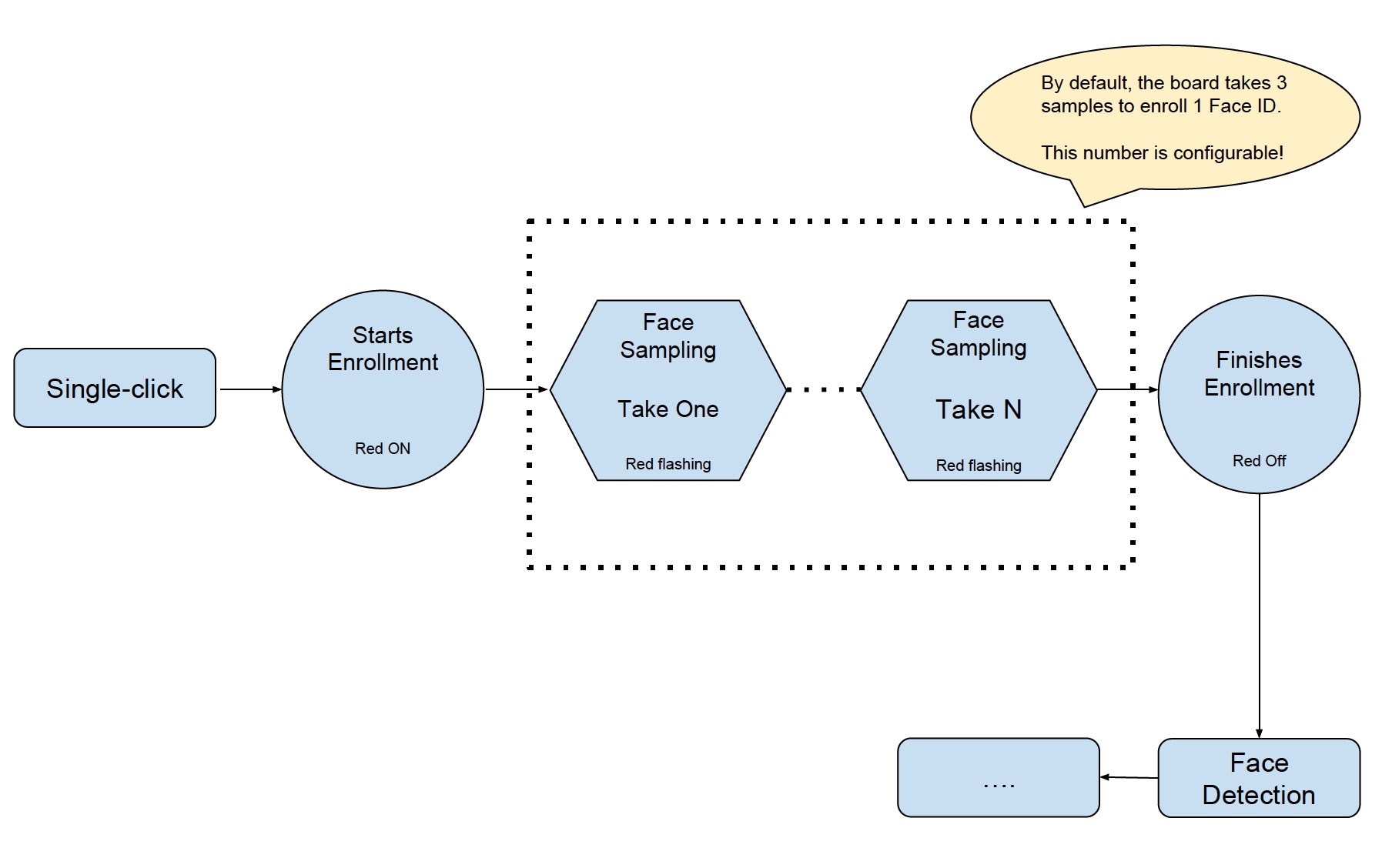
- Single-click the Side Tactile Button to enroll a new Face ID. At this moment, the red LED is on, and the browser displays START ENROLLING;
- Stand in front of the camera, and the face sampling starts automatically. The red LED flashes whenever the board gets a face sample, and the browser displays the numerical order of the current face sample, such as THE 1st SAMPLE. By default, the board has to take three samples to add one Face ID. Users can configure the number of samples needed for one Face ID. (Please adjust your position/distance from the camera and try again if you don't see the red LED flashing for a long time).
- After the Face ID enrollment, the red LED on the board is off and the browser displays ENROLLED FACE ID XXX;
- The board enters Face Detection after the Face ID enrollment.
Currently, ESP-EYE can enroll up to 10 Face IDs. Please note that the maximum number of enrolled Face IDs can be configured based on how the users allocate the flash memory. However, we recommend a number that is no greater than 30.
5.2 Delete a Face ID
- Double-click the Side Tactile Button to delete an existing Face ID;
- After that, the board deletes the earliest record of all the existing enrolled Face ID. The white LED on the board flashes, and the browser displays: XXX ID(S) LEFT.
Troubleshooting
The board returns to the status of "waiting to be woken up" when there are any network anomalies, such as "network disconnection" and "network timeout".